More results...

The study of the Generation, propagation and recording of elastic waves that cause earthquakes on Earth and the sources that produce them is earthquake seismology.
Earthquakes are occurred due to the sudden release of energy on the Earth. 95% of earthquakes occur at the boundaries of the lithosphere plates. Lithosphere plates are moving over the molten rock of the asthenosphere.
Due to the movement of the molten material of the mantel, lithosphere plates are moving apart, interacting together, or sliding past each other. When plates are moving, interactions between the plates occur along the plate boundaries. Due to these interactions, earthquakes, volcanism, mountain building, and island formation can occur along plate boundaries.
According to the movements of the plates, the plate boundaries are three types.
At the divergent boundaries, plates are moving apart. Molten rock of the mantle flows upward. The earth’s crust is pushed upward by the rising hot rock. Due to the movements of the mantle material, the crust of the earth stretches, wraps, and sometimes cracks.
As the molten rock breaks through the crust, the crust becomes thinner and volcanic activity takes place. Volcanic activities that occur undersea, form undersea mountain ranges. These are called oceanic ridges.
When plates move away, the molten rock of the mantle flows upward and cools. It forms a new sea floor (seafloor spreading)

At the convergent plate boundaries, plates move toward each other. The crust can be divided into two types as oceanic and continental. So, there is three possible plate convergence.

Oceanic crust aka basaltic rock is denser than continental crust aka granitic rock. When a convergence between an oceanic plate and a continental plate occurs, the oceanic plate slips under the continental plate. The region under the slip is called the subduction zone.
As the oceanic plate slips under the continental plate, it bends downward. These bends produce oceanic trenches. Mariana trench is the deepest known trench on Earth. It extends about 11 kilometers (7 miles) beneath the surface.
One oceanic plate subducts under the other plate. The results of oceanic-oceanic convergence are similar to the phenomena observed with oceanic-continental convergence. But here, volcanoes form on the sea floor.
Sustained volcanic activity results in dryland emerging from the ocean. These small volcanic islands are called island arcs (e.g., Aleutian, Mariana, and Tonga islands). Island arcs can continue to grow in size and elevation (e.g. Japan and the Philippines)
Here, subduction does not occur. The two plates collided. Due to the collision, the earth's crust will fracture. India collided with Asia to produce the Himalayas in such a convergence.
Tectonic plates slide past each other plates at transform plate boundaries as shown in figure 03.
Sections of rock can lock along the plate boundary (fault line). But when additional strain occurs, the rocks eventually shatter to produce earthquakes. A good example of such a fault is the San Andreas Fault, where the North American Plate and the Pacific Plate meet.

An earth fault is a fracture between two blocks of earth rocks. Those two blocks that are located next to each other are moved relative to each other. These motions may be rapid or slow and they can extend from a few millimeters to thousands of kilometers. Rapid faults cause earthquakes.

The first motion of the P waves observed on seismometers located in different directions of the earthquake provides information about the orientation of the fault. The geometry of the fault is called the focal mechanism.

Fault planes do have not smooth surfaces. If a fault surface is very smooth, the rupture would spread very smoothly the ground motion becomes very gentle, and the earthquake shaking is not so dangerous. But usually, fault surfaces are very rough. Due to the roughness of the surface, jolted motions are generated. So, it makes strong shaking when an earthquake.

The Generation, propagation, and recording of elastic waves on Earth and the sources that produce them are studied in seismology. The internal structure of the Earth can also be studied using variations of the gravity and magnetic fields of the Earth. But Seismology is the most powerful indirect method for studying the Earth’s interior. Groundwater resources, and economic resources like hydrocarbon and mineral oil deposits, can be revealed by using Seismology.
Seismic waves are longitudinal or transverse waves that travel through the inside or surface of the earth. Seismic waves are naturally occurring or artificially generated. Seismic waves are generated artificially by Vibroseis -vibrators, Artificial explosions, or air guns (Ocean Bottom Seismograph - OBS). These artificial seismic waves are used to study the interior of the earth and reveal the location of economic resources like hydrocarbon and mineral deposits.
Natural seismic waves occur due to earthquakes. Several types of earthquakes happen due to several reasons.
Seismic waves are of two types.
Body waves travel both surface and inside of the earth. There are two types of body waves. Those types are primary waves (P waves) and secondary waves or shear waves (S waves).
P waves (primary waves) are longitudinal waves and S waves (secondary waves) are transverse waves. P waves move the ground up and down while S waves move the ground horizontally. S waves cause much damage to the earth. The velocity of the P waves is higher than the S waves.
Velocities of P and S waves can be given,

Where,
Surface waves are confined only to the surface of the earth. there are two types of surface waves. Those two types of surface waves are called 'Love waves and Rayleigh waves.'
All seismic waves obey Snell`s laws.

Also, the earth is not an elastic and isotropic medium. Therefore, seismic waves attenuate or decrease in amplitude as they propagate. At the discrete interface, the amplitude of the wave is reduced due to the reflection and transmission. Other processes that can reduce wave amplitudes are,
To study the interior of the earth, artificial seismic waves are generated. These waves travel through the earth and are received by seismic receivers (Geophones). If the earth is a homogeneous medium, the seismic waves can be observed only through direct P and S waves in each station record. However, real earth is heterogeneous and there are many layer boundaries. So, we will observe various types of later phases.

Where,
The size of an earthquake can be measured by “Seismic intensity scale” (seismic intensity at a given location) or “Magnitude scale” (magnitude at the epicenter).
The first way to describe the size of an earthquake is in terms of its intensity at a given location. The intensity is based on observations on the Earth’s surface of damages to buildings and ground effects. The intensity of the epicenter is considered the maximum intensity of the scale. Several intensity scales,
The earthquake magnitude scale is based on the measurement of the energy released by an earthquake. The Richter scale is a well-known scale that is used to measure the magnitude of an earthquake. This method was first introduced by Charles Richter in 1935. The local magnitude (ML) of an earthquake is given by,

Richter has made a table for log10A0
| Δ (km) | -log10A0 | Δ (km) | -log10A0 | Δ (km) | -log10A0 |
| 0 | 1.4 | 150 | 3.3 | 390 | 4.4 |
| 5 | 1.4 | 160 | 3.3 | 400 | 4.5 |
| 10 | 1.5 | 170 | 3.4 | 410 | 4.5 |
| 15 | 1.6 | 180 | 3.4 | 420 | 4.5 |
| 20 | 1.7 | 190 | 3.5 | 430 | 4.6 |
| 25 | 1.9 | 200 | 3.5 | 440 | 4.6 |
| 30 | 2.1 | 210 | 3.6 | 450 | 4.6 |
| 35 | 2.3 | 220 | 3.65 | 460 | 4.6 |
| 40 | 2.4 | 230 | 3.7 | 470 | 4.7 |
| 45 | 2.5 | 240 | 3.7 | 480 | 4.7 |
| 50 | 2.6 | 250 | 3.8 | 490 | 4.7 |
| 55 | 2.7 | 260 | 3.8 | 500 | 4.7 |
| 60 | 2.8 | 270 | 3.9 | 510 | 4.8 |
| 65 | 2.8 | 280 | 3.9 | 520 | 4.8 |
| 70 | 2.8 | 290 | 4.0 | 530 | 4.8 |
| 80 | 2.9 | 300 | 4.0 | 540 | 4.8 |
| 85 | 2.9 | 310 | 4.1 | 550 | 4.8 |
| 90 | 3.0 | 320 | 4.1 | 560 | 4.9 |
| 95 | 3.0 | 330 | 4.2 | 570 | 4.9 |
| 100 | 3.0 | 340 | 4.2 | 580 | 4.9 |
| 110 | 3.1 | 350 | 4.3 | 590 | 4.9 |
| 120 | 3.1 | 360 | 4.3 | 600 | 4.9 |
| 130 | 3.2 | 370 | 4.3 | ||
| 140 | 3.2 | 380 | 4.4 |
| Richter number | Increase in magnitude |
| 1 | 1 |
| 2 | 10 |
| 3 | 100 |
| 4 | 1000 |
| 5 | 10000 |
| 6 | 100000 |
| 7 | 1000000 |
| 8 | 10000000 |
| 9 | 100000000 |
| Magnitude | Description | Average effect | Frequency (Per year) |
| 1.0 – 1.9 | Micro | Microearthquakes can be recorded by seismographs. But the microearthquakes cannot be felt by people. | Several millions |
| 2.0 – 2.9 | Minor | Not felt or slightly felt by some people. But no damage. | About one million |
| 3.0 – 3.9 | Minor | The shaking of objects is noticeable. Often felt by people. | More than 100,000 |
| 4.0 – 4.9 | Light | Felt by most people. A noise and shaking of objects can be observed. | 10,000 - 15,000 |
| 5.0 – 5.9 | Moderate | Can damage poor constructions. Felt by everyone | 1000 - 1500 |
| 6.0 – 6.9 | Strong | Can damage a moderate number of well-built constructions. | 100 - 150 |
| 7.0 – 7.9 | Major | Felt people within a distance of about 250km from the epicenter. Considerable damage to the buildings. | 10 - 20 |
| 8.0 – 8.9 | Great | Major damage to the buildings. And the damage occurs over a large area. | 1 |
| 9.0 – 9.9 | Great | Destruction of several damages to the buildings. The earthquake can be felt by people in large areas. These earthquakes permanently change the earth's topography. | One per 10 to 50 years |

USGS - What is a fault and what are the different types?
www.ucl.ac.uk - Seismic Waves
www.semanticscholar.org - The Richter scale
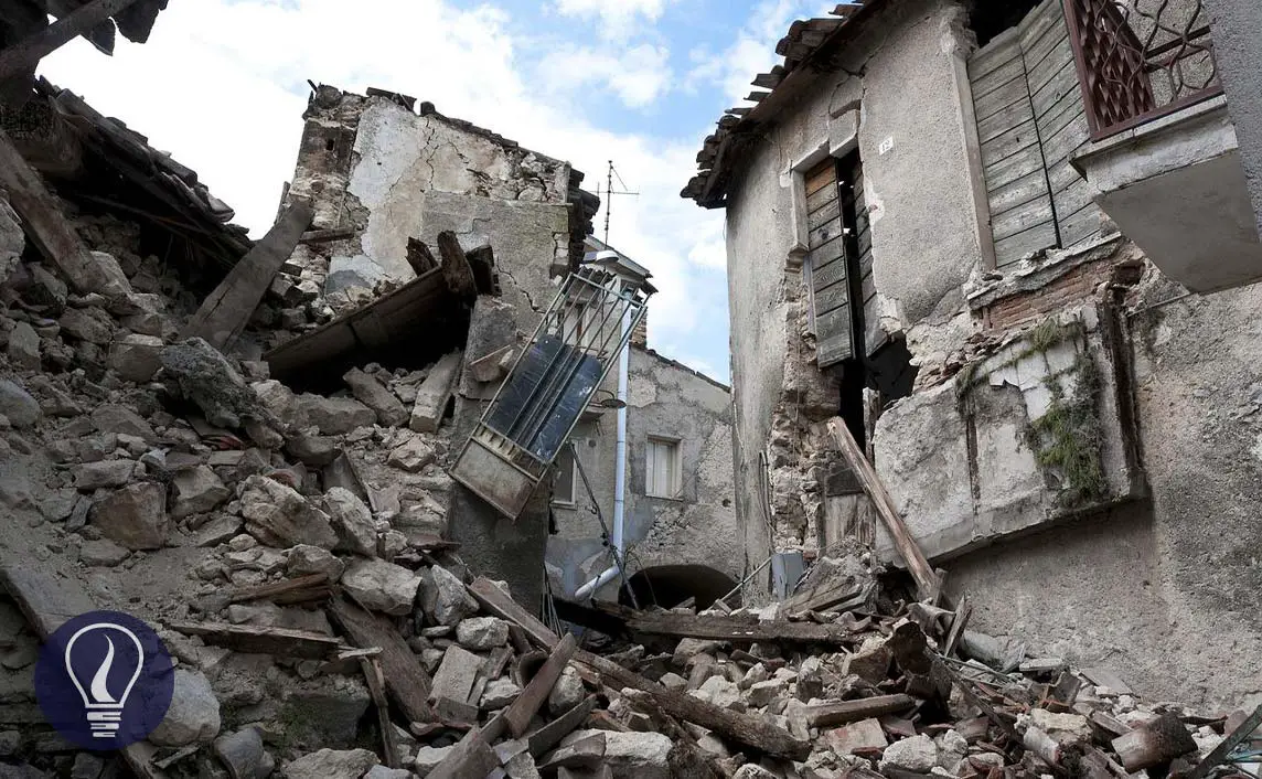
The cover image was created using an Image by Angelo Giordano from Pixabay
Figure 01: Contains an image by domdomegg, licensed under CC BY 4.0, via Wikimedia Commons
Figure 02: Contains an image by domdomegg, licensed under CC BY 4.0, via Wikimedia Commons
Figure 03: Contains an image by domdomegg, licensed under CC BY 4.0, via Wikimedia Commons
Figure 07: Contains an image by Nicoguaro, licensed under CC BY 4.0, via Wikimedia Commons
Figure 07: Contains an image by すじにくシチュー, licensed under CC0, via Wikimedia Commons
Figure 07: Contains an image by すじにくシチュー, licensed under CC0, via Wikimedia Commons
Figure 07: Contains an image by Д.Ильин: vectorization, licensed under CC0, via Wikimedia Commons