More results...

Inverting amplifier or inverting operational amplifier is a type of op-amp configuration, where the input voltage is changed in the opposite direction. Therefore, the output signal is out of phase by 180°.

In an operational amplifier, there are two inputs. They are inverting input and non-inverting input. Generally, the inverting input is indicated using the (-) sign, and the non-inverting input is indicated using the (+) sign.
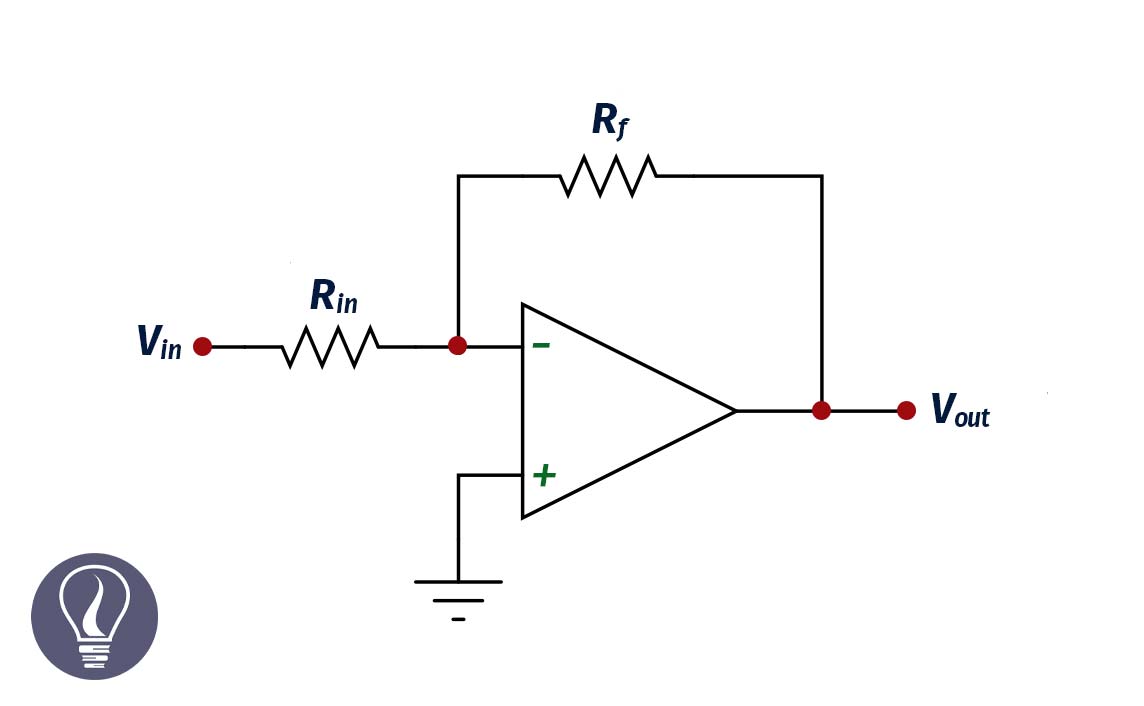
In the inverting amplifier configuration, the non-inverting terminal has been grounded. The input signal is applied to the inverting terminal (indicated by the '-' sign).
In this circuit, a fraction of the output current is feedback to the input through a resistor.

In an ideal op amp, there is no voltage difference between the inverting and non-inverting terminal. Therefore,

Since the non-inverting terminal has been grounded, V+ is zero. Therefore,

Let’s apply the Kirchhoff law for Vin,

Applying the Kirchhoff law to the Vout,

Open loop gain can be calculated using Equation 1 and Equation 2.

The open loop gain, of an inverting amplifier depends on the ratio between the two resistors. And it is independent of the closed-loop gain.
The equivalent circuit is the circuit that is constructed using capacitors, resistors, inductors, etc, and gives the same result as the original component. The equivalent circuit for a non-ideal inverting amplifier can be used to calculate the non-ideal voltage gain.
There are two configurations of inverting op amps and they are open loop configuration and closed loop configuration.

In an ideal situation, there is no current flow through the circuit. But there is a current flow in a real situation. Using Kirchhoff’s law, we can write expressions for I, I1, and I2 as follows in a closed-loop configuration.

Where,

Now let’s consider the open loop configuration. In the ideal open loop configuration, the output voltage can be expressed as follows.

Where A is the ideal voltage gain. But in real situations, there is an additional voltage due to the output impedance. Therefore, the output voltage can be written as follows.

Where Ro is the output impedance. By using the above equation, we can derive an expression for I1.

Same as the closed-loop configuration,

From Equation 1 and Equation 2, we can get an expression for Vout.

In an inverting amplifier, the non-inverting terminal has been grounded. Therefore, V+ is zero.

Now we can derive an expression for Vin using equation 1.

In the above equation, Vout can be substituted by equation 3.

The voltage gain of an op-amp is the ratio between Vout and Vin. Using equations 3 and 4 we can get an expression for the voltage gain.

We can divide both the upper and lower parts of the equation by A.

The above expression tells us the voltage gain of a non-ideal inverting amplifier. We can apply the above equation to the ideal situation also. In the ideal situation, A and Rin are infinite. And Ro is approximately zero.


The cover image was designed using an image by Alejo2083, licensed under CC BY-SA 3.0, via Wikimedia Commons
Figure 02: Contains an image by Alejo2083, licensed under CC BY-SA 3.0, via Wikimedia Commons